Robot Coding
Here we show how to use EusLisp in robot programming.
This is based on the samplerobot provided by hrpsys_ros_bridge_tutorials.
In the case install was performed using jsk_common, hrpsys is also installed.
The explanation here is appliable to any robot that follows the robot model and interface base, such as hrpsys_ros_bridge and jsk_robot. The example below can be used for other robots by replacing the samplerobot and *sr* parts.
Sample robot start-up
First, launch roscore.
roscore
Then, in a different terminal move to the proper directory.
roscd hrpsys_ros_bridge_tutorials/euslisp
If you are unable to use the above, there is the possibility that the terminal has not been source'd or that the install was not done correctly.
Next, run emacs shell with M-x shell and run the interpreter loading samplerobot-interface.l.
roseus samplerobot-interface.l
When the prompt returns, doing the following completes the preparation.
(samplerobot-init)
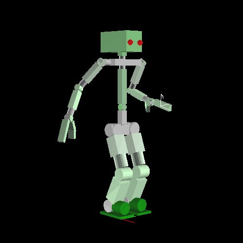
After a few seconds, the simulator should be launched.
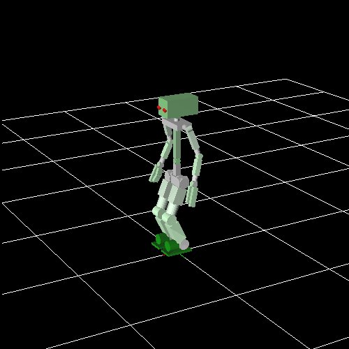
This simulator is not a part of EusLisp. When using the real robot or a different kind of simulator like gazebo, this window does not show up.
Here, the robot object and the robot interface are bound to the global variables *sr* and *ri*, respectively.
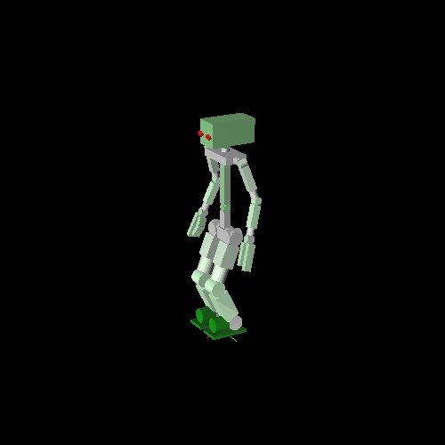
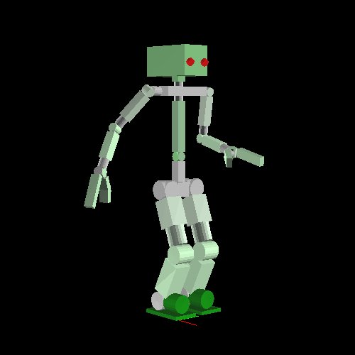
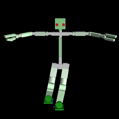
Executing objects launches the irtviewer, showing EusLisp robot model.
(objects (list *sr*))
Both windows can be distinguished by the title and grid.
Programming using the robot model
Predefined poses
Each robot has a set of predefined poses.
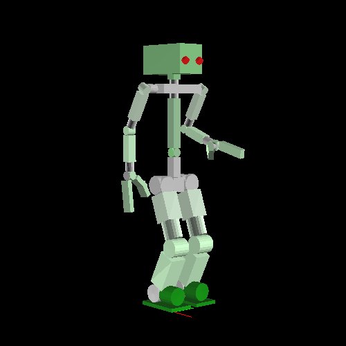
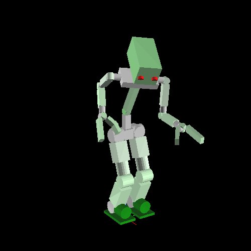
For instance, the following manipulation pose.
(send *sr* :reset-manip-pose)

Or the default pose:
(send *sr* :reset-pose)
Access to each limb
For example, to access the right arm:
(send *sr* :rarm)
This returns a list of all links in the right arm:
(#<bodyset-link #X7344798 RARM_LINK1 0.0 -210.0 1249.5 / 0.0 0.524 0.0> #<bodyset-link #X73367b0 RARM_LINK2 0.0 -210.0 1249.5 / 0.0 0.524 0.0> #<bodyset-link #X7309358 RARM_LINK3 -131.5 -210.0 1021.735 / 0.0 0.524 0.0> #<bodyset-link #X72ed1b8 RARM_LINK4 -131.5 -210.0 1021.735 / 0.0 -1.222 0.0> #<bodyset-link #X72b9da8 RARM_LINK5 100.604 -210.0 937.256 / 0.434 -1.189 -0.406> #<bodyset-link #X72a27e0 RARM_LINK6 100.604 -210.0 937.256 / 0.596 -1.29 -0.559> #<bodyset-link #X7253560 RARM_LINK7 100.604 -210.0 937.256 / 0.596 -1.29 0.078>)
For other limbs:
(send *sr* :head)  ;; samplerobot does not have any head links
(send *sr* :larm)
(send *sr* :body)
(send *sr* :rleg)
(send *sr* :lleg)
Obviously, each robot does not necessarily have all of the above limbs. For instance, robots with mobile platforms do not have legs.
Joints of each limb can be listed like in the following.
(send *sr* :rarm :joint-list)

;; (#<rotational-joint #X70a3cd8 RARM_SHOULDER_P> #<rotational-joint #X76107a0 RARM_SHOULDER_R> #<rotational-joint #X7610668 RARM_SHOULDER_Y> #<rotational-joint #X76105a8 RARM_ELBOW> #<rotational-joint #X7610470 RARM_WRIST_Y> #<rotational-joint #X76103b0 RARM_WRIST_P> #<rotational-joint #X7610278 RARM_WRIST_R>)
Each joint can be directly accessed by its real name or by EusLisp nickname. In this case, nicknames are given by replacing _ with - in each name. All of the forms below are equivalent.
(send *sr* :rarm_shoulder_p)
(send *sr* :rarm-shoulder-p)
(send *sr* :rarm :shoulder-p)
Forward Kinematics
The following shows how to get the angle of a particular joint. The result is in degrees.
(send *sr* :rarm :elbow-p :joint-angle)
Giving an argument to the above sets the angle to the given value.
(send *sr* :rarm :elbow-p :joint-angle -30.0)
Arbitrary poses can be created by setting joint angles this way.
(send *sr* :rarm :shoulder-r :joint-angle -30.0)
Inverse Kinematics
Next we will solve the Inverse Kinematics (IK).
The base coordinates for the IK are given by :end-coords method.
(send *sr* :larm :end-coords)
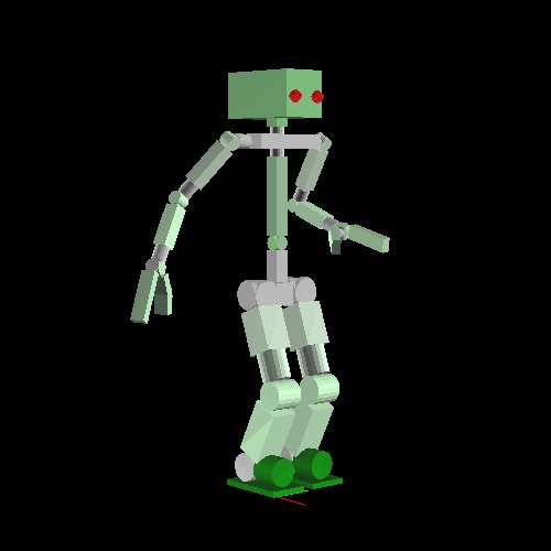
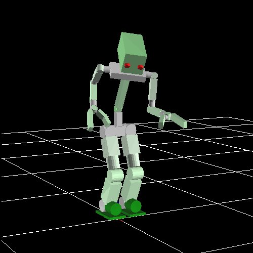
And can be temporarily visualized with the following.
(send *sr* :larm :end-coords :draw-on :size 100.0 :flush t)
Here, the arrow shows the Z axis. Below we show how to copy and move this coordinate, making the robot move its hand to the desired point.
(setq *larm-end* (send *sr* :larm :end-coords :copy-worldcoords))
(send *larm-end* :translate (float-vector 100.0 0.0 10.0))
(send *sr* :larm :inverse-kinematics *larm-end*)
This time, the IK was solved in order to completely match the base coordinate with the goal coordinate, both in position and attitude.
However, when thinking on grasping a cylindrical object like a pet bottle, for instance, arbitrary rotation on the Z axis is tolerated.
We indicate such cases by using the keyword :rotation-axis:
- t is the default value, meaning complete match.
- :z means arbitrary rotation on the Z axis.
- nil means to ignore rotation, matching only the position.
(send *larm-end* :translate (float-vector 100.0 0.0 50.0))
(send *sr* :larm :inverse-kinematics *larm-end* :rotation-axis :z)
:move-end-pos can also be used for displacing the position in a simple way.
Here, a vector relative to the end-coords is given as argument.
(send *sr* :larm :move-end-pos (float-vector 0 0 100))
The three examples above move only the arm, but it is also possible to use the upper body as well, amplifying the reachability.
In order to do so, it is necessary to use :torso t and set :link-list to the list of all links to be used in the calculation.
(send *sr* :reset-manip-pose)
(setq *larm-end* (send *sr* :larm :end-coords :copy-worldcoords))
(send *larm-end* :translate (float-vector 400.0 -50.0 50.0))
(send *sr* :larm :inverse-kinematics *larm-end*
        :rotation-axis t :torso t
        :link-list
      (send *sr* :link-list
            (send *sr* :larm :end-coords :parent)
            (car (send *sr* :torso :links))))
Communication with the robot
The robot interface *ri* is used to perform communication with the robot (real robot or simulator).
The following synchronizes the joint angles of the robot with the ones of the model.
(send *ri* :angle-vector (send *sr* :angle-vector) 2000)
The above makes the robot move to the goal pose in 2000ms.
Pose transition is performed asynchronously, so when synchronization is necessary :wait-interpolation is used.
(send *ri* :wait-interpolation)
To send the joint angles of the robot to the model, on the other hand, the following is used.
(send *ri* :state)
(send *sr* :angle-vector (send *ri* :potentio-vector))
Using the legs
:fix-leg-to-coords is used to make the robot move to a certain spot.
(send *sr* :fix-leg-to-coords (make-coords) :both)
Here, :both means to match the center of both legs to the given coordinate.
:rleg and :lleg can also be used, matching the center of right and left foot, respectively.
With bipedal robots, it is possible to calculate the static balance and move the legs in order to make the center of mass match the center of the support polygon.
(send *sr* :reset-pose)
(send *sr* :rarm :shoulder-r :joint-angle -90)
(send *sr* :larm :shoulder-r :joint-angle 90)
(send *sr* :rleg :move-end-pos (float-vector 0 -100 100))
(send *sr* :move-centroid-on-foot :lleg '(:lleg))
The above shows how to move the center of mass into the left leg.
First argument of :move-centroid-on-foot indicates on which leg the center of mass should be moved into, and the second argument indicates which legs should be moved.